Multiprocessors
Introduction to Multiprocessors
The objectives of this module are to discuss the different types of parallel processors and the main issues to be considered while designing parallel processors.
We know that there are different types of parallelism that applications exhibit and the architectures try to exploit them. In our earlier modules, we have looked at different techniques to exploit ILP. We have also looked at how thread level parallelism can be exploited using fine grained and coarse grained multithreading. Both ILP and TLP can be combined with SMT. However, when SMT is employed, the single thread performance is likely to go down as the caches, branch predictors, registers, etc. are shared. This effect can be mitigated by trying to prioritize or prefer one or two threads. There are several design challenges associated with SMT, as shown below:
• How many threads?
– Many to find enough parallelism
– However, mixing many threads will compromise execution of individual threads
• Processor front-end (instruction fetch)
– Fetch as far as possible in a single thread (to maximize thread performance)
– However, this limits the number of instructions available for scheduling from other threads
• Larger register files needed
– In order to store multiple contexts
• Minimize clock cycle time
– Not affecting the clock cycle, particularly in critical steps such as instruction issue, where more candidate instructions need to be considered, and in Instruction completion, where choosing what instructions to commit may be challenging
• Cache conflicts
– Ensuring that the cache and TLB conflicts generated by the simultaneous execution of multiple threads do not cause significant performance degradation
• At the end of the day, it is only a single physical processor
– Though SMT enables better threading (e.g. up to 30%), OS and applications perceive each simultaneous thread as a separate “virtual processor”, the chip has only a single copy of each resource
• Difficult to make single-core clock frequencies even higher
• Deeply pipelined circuits:
– Heat problems
– Clock problems
– Efficiency (Stall) problems
• Doubling issue rates above today’s 3-6 instructions per clock, say to 6 to 12 instructions, is extremely difficult
– issue 3 or 4 data memory accesses per cycle,
– rename and access more than 20 registers per cycle, and
– fetch 12 to 24 instructions per cycle
It has been shown that with eight threads in a processor with many resources, SMT yields throughput improvements of roughly 2-4. Alpha 21464, IBM Power5 and Intel Pentium 4 are examples of SMT.
The challenges associated with SMT and a slowdown in uniprocessor performance arising from diminishing returns in exploiting ILP, combined with growing concern over power, is leading to a new era in computer architecture – an era where multiprocessors play a major role. This is also reinforced by other factors like:
• Increasing interest in servers and server performance
• Applications becoming more and more data-intensive
• The insight that increasing performance on the desktop is less important for many applications
• An improved understanding of how to use multiprocessors effectively
• The advantages of leveraging a design investment by replication rather than unique design—all multiprocessor designs provide such leverage
Thus, Multi-core architectures have come to dominate the market. Here, there are several cores, where each is smaller and not as powerful (but also easier to design and manufacture). They are however, great with thread-level parallelism. On the other hand, SMT processors can have one large and fast superscalar core, which has great performance on a single thread and mostly still only exploits instruction-level parallelism.
The traditional definition of a parallel computer goes like this: “A parallel computer is a collection of processing elements that cooperate and communicate to solve large problems fast” (Almasi and Gottlieb, Highly Parallel Computing *,*1989). Whenever we talk of parallel computers, the popular questions to be answered are:
– How large a collection?
– How powerful are processing elements?
– How do they cooperate and communicate?
– How are data transmitted?
– What type of interconnection?
– What are the HW and SW primitives for the programmer?
– What is the programming model?
– How does it translate into performance?
We shall try to answer most of these questions in this module and some of the subsequent modules.
Taxonomy of computers: First of all, we shall look at how computer systems are classified based on the number of instruction streams and data streams by Michael Flynn. According to him, computers can be put into one of four categories:
1. Single instruction stream, single data stream (SISD) – This category is the uniprocessor.
2. Single instruction stream, multiple data streams (SIMD) – The same instruction is executed by multiple processors using different data streams. SIMD computers exploit data-level parallelism by applying the same operations to multiple items of data in parallel. Each processor has its own data memory (hence multiple data), but there is a single instruction memory and control processor, which fetches and dispatches instructions. For applications that display significant data-level parallelism, the SIMD approach can be very efficient. The multimedia extensions available in processor ISAs are a form of SIMD parallelism. Vector architectures, are the largest class of SIMD architectures. Examples of SIMD style of architectures include the Illiac-IV and CM-2. They have the following characteristics:
i. Simple programming model
ii. Low overhead
iii. Flexibility
iv. All custom integrated circuits
We shall discuss all the different ways of exploiting data-level parallelism in a later module.
3. Multiple instruction streams, single data stream (MISD) – No commercial multiprocessor of this type has been built to date.
4. Multiple instruction streams, multiple data streams (MIMD) – Each processor fetches its own instructions and operates on its own data. MIMD computers exploit thread-level parallelism, since multiple threads operate in parallel. In general, thread-level parallelism is more flexible than data -level parallelism and thus more generally applicable. Examples include Sun Enterprise 5000, Cray T3D and SGI Origin. They are
i. Flexible
ii. Use off-the-shelf microprocessors and hence have the cost/performance advantage
iii. Most common parallel computing platform Multicore processors fall under this category.
We shall discuss the MIMD style of architectures in this module.
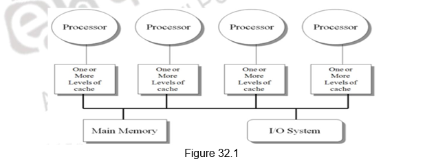
Classes of MIMD architectures: There are basically two types of MIMD architectures, depending on the number of processors involved, which in turn dictates a memory organization and interconnect strategy. We classify multiprocessors based on their memory organization as centralized shared-memory architectures and distributed shared memory architectures. The centralized shared memory architectures normally have a few processors sharing a single centralized memory through a bus based interconnect or a switch. With large caches, a single memory, possibly with multiple banks, can satisfy the memory demands of a small number of processors. However, scalability is limited as sharing a centralized memory becomes very cumbersome as the number of processors increases. Because there is a single main memory, it has a symmetric relationship to all processors and a uniform access time from any processor, and these multiprocessors are most often called symmetric (shared-memory) multiprocessors (SMPs), and this style of architecture is also called uniform memory access (UMA), arising from the fact that all processors have a uniform latency from memory, even if the memory is organized into multiple banks. Figure 32.1 shows the organization of such multiprocessors.
The second class consists of multiprocessors with physically distributed memory. Figure 32.2 shows what these multiprocessors look like. In order to handle the scalability problem, the memory must be distributed among the processors rather than centralized. Each processor has its own local memory and can also access the memory of other processors. The larger number of processors also raises the need for a high-bandwidth interconnect.
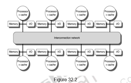
Distributing the memory among the nodes has two major benefits. First, it is a cost-effective way to scale the memory bandwidth if most of the accesses are to the local memory in the node. Second, it reduces the latency for accesses to the local memory. These two advantages make distributed memory attractive. The disadvantages for distributed memory architectures are that communicating data between processors becomes more complex, and that it requires more effort in the software to take advantage of the increased memory bandwidth afforded by the distributed memories. The comparison between the two styles of architecture is given below:
- Centralized shared memory architectures
- Uniform memory access time – UMA processors
- Symmetric processors – Symmetric Shared Memory multiprocessors (SMPs)
- Interconnection is traditionally through a bus – scalability problem
- Simpler software model
- Decentralized or distributed memory architectures
- Non-uniform memory access time – NUMA processors
- Get more memory bandwidth, lower memory latency
- Drawback: Longer communication latency
- Drawback: Software model more complex
Models for Communication: As we have seen, in order to handle the scalability problem, we need to distribute the memory among multiple processors. The use of distributed memory leads to two different paradigms for inter-processor communication, transferring data from one processor to another – shared memory model and message passing model. The comparison between the two models is given below.
1. Shared Memory with “Non Uniform Memory Access” time (NUMA)
- There is logically one address space and the communication happens through the shared address space, as in the case of a symmetric shared memory architecture. One processor writes the data in a shared location and the other processor reads it from the shared location.
2. Message passing “multicomputer” with separate address space per processor
• Each processor has its own address space. It is still NUMA style of architecture. In this case, we can invoke software with Remote Procedure Calls (RPC).
• This is normally done through libraries such as MPI (Message Passing Interface).
• Also called “Synchronous communication” since communication causes synchronization between 2 processes.
Advantages of Shared-memory communication model: Based on the above discussion, the advantages of both the communication models can be presented. The shared memory model has the following advantages:
1. This model has compatibility with the SMP hardware.
2. There is ease of programming when communication patterns are complex or vary dynamically during execution.
3. This model lends the ability to develop applications using the familiar SMP model, with attention only on performance critical accesses .
4. There is lower communication overhead and better use of bandwidth for small items, due to the implicit communication and memory mapping to implement protection in hardware, rather than through the I/O system.
5. The use of HW-controlled caching to reduce remote communication by caching of all data, both shared and private.
Advantages of Message-passing communication model: The message passing communication model has the following advantages:
1. The hardware can be simpler. (esp. vs. NUMA)
2. The communication is explicit, which means it is simpler to understand; in shared memory it can be hard to know when communicating and when not, and how costly it is.
3. The explicit communication focuses computation, sometimes leading to programs. attention on costly aspects of parallel improved structure in multiprocessor
4. Synchronization is naturally associated with sending messages, reducing the possibility for errors introduced by incorrect synchronization
5. Easier to use sender-initiated communication, which may have some advantages in performance
Data parallel model: Yet another programming model, whose architectural features we shall discuss in detail later is the data parallel model. Its salient features are listed below:
1. Here, operations can be performed in parallel on each element of a large regular data structure, such as an array.
2. There is one Control Processor that broadcasts to many Processing Elements.
3. There is support for a condition flag per PE so that it can be skipped for certain operations.
4. The data is distributed in each memory.
5. There are data parallel programming languages that lay out data to the processing elements.
6. This SIMD programming model led to the Single Program Multiple Data (SPMD) model, where all processors execute identical programs.
Programming Model Summary: Programming model is the conceptualization of the machine that the programmer uses in coding applications. It basically defines how parts cooperate and coordinate their activities. It also specifies communication and synchronization operations . The various programming models that we have discussed can be summarized as:
• Multiprogramming
– no communication or synchronization at program level
• Shared address space
– like bulletin board
• Message passing
– like letters or phone calls, explicit point to point
• Data parallel:
– more regimented, global actions on data
– implemented with shared address space or message passing
Performance metrics for communication mechanisms: Having looked at the different styles of multiprocessor architectures, we shall now focus on the performance metrics used to evaluate such systems. Performance of multi processor systems is evaluated based on the communication bandwidth, communication latency and techniques used for hiding the communication latency.
1. Communication Bandwidth
– We generally need high bandwidth in communication.
– This is limited by processor, memory and interconnection bandwidth.
2. Communication Latency
– This affects performance, since processor may have to wait for the data to arrive.
– It affects ease of programming, since requires more thought to overlap communication and computation.
– The overhead to communicate is a problem in many machines .
3. Communication Latency Hiding
– What are the mechanisms that will help hide latency?
– This increases programming system burden. Examples include overlapping the message send with computation, prefetching data, switching to other tasks, etc.
Therefore, whichever style of architecture gives high communication bandwidth, low communication latency and supports techniques for hiding communication latency are preferred.
Challenges of parallel processing: When we look at multiprocessor systems, we may run varied tasks ranging from independent tasks requiring no communication at all, to tasks that may require lots of communication among themselves . Therefore, there are two important hurdles that make parallel processing challenging. They are the amount of parallelism available in programs and the communication overhead. Both of these are explainable with Amdahl’s Law, The degree to which these hurdles are difficult or easy is determined both by the application and by the underlying architecture.
The first hurdle has to do with the limited parallelism generally available in programs Limitations in available parallelism make it difficult to achieve good speedups in any parallel processor. The importance of parallelism in programs is illustrated through the following example. Suppose we want to achieve an overall speedup of 80 with 100 processors. In such a scenario, we can calculate the fraction of the original computation that can be sequential. Applying this to Amdahl’s Law, and assuming that the program operates in only two modes – parallel with all processors fully used, which is the enhanced mode, or serial with only one processor in use, we find that only 0.25% of the program should be sequential. That is, to achieve a speedup of 80 with 100 processors, only 0.25% of original computation can be sequential. That shows us the importance of writing parallel programs to harness the power of the multiple processors. In practice, programs do not just operate in fully parallel or sequential mode, but often use less than the full complement of the processors when running in parallel mode.
The second challenge is the relatively high cost of communication among processors. If we consider a 32-processor multiprocessor operating at 1 GHz. and only 0.2% of the instructions involve a remote communication reference which takes 400ns / access, it can be shown even with the most optimistic calculations, that if the remote references are not there, the multiprocessor will be 2.6 times faster. Such is the effect of communication overhead and this has to be ha ndled appropriately.
One solution to reduce the communication overhead is to make use of caches and cache the data needed by every processor. Caches serve to Increase the bandwidth and reduce the latency of access. They are valuable for both private data and shared data. However, there are problems like cache consistency that we have to deal with. This will be elaborated in the subsequent modules.
To summarize, we have looked at the need for multiprocessor systems. The limitations of ILP and TLP as well as power and heat constraints have made us shift from complex uniprocessors to simpler multicores. There are different styles of parallel architectures. We have discussed the major categories along with their advantages and disadvantages. There are also different programming models available. Finally, we have discussed the main challenges associated with multiprocessor systems.
Web Links / Supporting Materials
- Computer Organization and Design – The Hardware / Software Interface, David A. Patterson and John L. Hennessy, 4th Edition, Morgan Kaufmann, Elsevier, 2009.
- Computer Architecture – A Quantitative Approach , John L. Hennessy and David A.Patterson, 5th Edition, Morgan Kaufmann, Elsevier, 2011.
Cache Coherence I
The objectives of this module are to discuss about the cache coherence problem in multiprocessors and elaborate on the snoop based cache coherence protocol.
In the previous module, we pointed out the challenges associated with multiprocessors.
The two main challenges that we pointed out are as follows:
1. Parallel and sequential portions of the program
• Our programs are going to have both sequential code and parallel code. As the sequential code increases, the performance of the multiprocessor is going to come down. Therefore, we need to write parallel programs that will harness the full power of the underlying parallel architecture.
2. Communication latency
• Communication latency among processors is going to be a major overhead and that has to be reduced. This can be done by caching the data in multiple processors. Caches serve to increase bandwidth and reduce latency of access and are useful for both private data and shared data.
However, when we cache data in multiple processors, we have the problem of cache coherence and consistency. We shall elaborate on that in detail in this module and the next module.
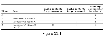
Multiprocessor Cache Coherence: Symmetric shared-memory machines usually support the caching of both shared and private data. Private data are used by a single processor, while shared data are used by multiple processors essentially providing communication among the processors through reads and writes of the shared data. When a private data is cached, its location is migrated to the cache, reducing the average access time as well as the memory bandwidth required. Since no other processor uses the data, the program behavior is identical to that in a uniprocessor. Similarly, when shared data are cached, the shared value may be replicated in multiple caches. In addition to the reduction in access latency and required memory bandwidth, this replication also provides a reduction in contention that may exist for shared data items that are being read by multiple processors simultaneously. Caching of shared data, however, introduces the cache coherence problem. This is because the shared data can have different values in different caches, and this has to be handled appropriately. Figure 33.1 illustrates the problem. We can see that both processors A and B read location X as 1. Later on, when processor A modifies it to value 0, processor B still has it as value 1. Thus, two different processors can have two different values for the same location. This difficulty is generally referred to as the cache coherence problem.
Informally, we could say that a memory system is coherent if any read of a data item returns the most recently written value of that data item. This simple definition contains two different aspects of memory system behavior, both of which are critical to writing correct shared-memory programs. The first aspect, called coherence, defines what values can be returned by a read. The second aspect, called consistency, determines when a written value will be returned by a read.
A memory system is coherent if the following hold good:
1. A read by a processor P to a location X that follows a write by P to X, with no writes of X by another processor occurring between the write and the read by P, always returns the value written by P.
2. A read by a processor to location X that follows a write by another processor to X returns the written value if the read and write are sufficiently separated in time and no other writes to X occur between the two accesses.
3. Writes to the same location are serialized; that is, two writes to the same location by any two processors are seen in the same order by all processors. This ensures that we do not see the older value after the ne wer value.
The first property simply preserves program order, which is true even in uniprocessors. The second property defines the notion of what it means to have a coherent view of memory. The third property ensures that writes are seen in the proper order.
Although the three properties just described are sufficient to ensure coherence, the question of when a written value will be seen is also important. We cannot expect that a read of X see the value written for X by some other processor, immediately. If, for example, a write of X on one processor precedes a read of X on another processor by a very small time, it may be impossible to ensure that the read returns the value of the data written, since the written data may not even have left the processor at that point. The issue of exactly when a written value must be seen by a reader is defined by a memory consistency model, which will be discussed in a later module. Coherence and consistency are complementary: Coherence defines the behavior of reads and writes to the same memory location, while consistency defines the behavior of reads and writes with respect to accesses to other memory locations.
Cache Coherency Protocols: Multiprocessors support the notion of migration, where data is migrated to the local cache and replication, where the same data is replicated in multiple caches. The cache coherence protocols ensure that there is a coherent view of data, with migration and replication. The key to implementing a cache coherence protocol is tracking the state of any sharing of a data block. There are two classes of protocols, which use different techniques to track the sharing status:
1. Directory based: The sharing status of a block of physical memory is kept in just one location, called the directory. The directory can also be distributed to improve scalability. Communication is established using point-to-point requests through the interconnection network.
2. Snoop based: Every cache that has a copy of the data from a block of physical memory also has a copy of the sharing status of the block, but no centralized state is kept. The caches are all accessible via some broadcast medium (a bus or switch), and all cache controllers monitor or snoop on the medium to determine whether or not they have a copy of a block that is requested on a bus or switch access. Requires broadcast, since caching information is at processors Useful for small scale machines (most of the market)
We will focus on the snoop based approach in this module.
Snoopy Cache Coherence Protocol: There are two ways to maintain the coherence requirement. One method is to ensure that a processor has exclusive access to a data item before it writes that item. This style of protocol is called a write invalidate protocol because it invalidates other copies on a write. It is the most common protocol, both for snooping and for directory schemes. Exclusive access ensures that no other readable or writable copies of an item exist when the write occurs: All other cached copies of the item are invalidated.
The alternative to write invalidate is the write broadcast or write update mechanism. Here, all the cached copies are updated simultaneously. This requires more bandwidth. Also, when multiple updates happen to the same location, unnecessary updates are done. However, there is lower latency between the write and the read. We shall assume a write invalidate approach for the rest of the discussion.
The bus is normally used to perform invalidates. To perform an invalidate, the processor simply acquires bus access and broadcasts the address to be invalidated on the bus. All processors continuously snoop on the bus, watching the addresses. The processors check whether the address on the bus is in their cache. If so, the corresponding data in the cache are invalidated. When a write to a block that is shared occurs, the writing processor must acquire bus access to broadcast its invalidation. If two processors attempt to write shared blocks at the same time, their attempts to broadcast an invalidate operation will be serialized when they arbitrate for the bus. The first processor to obtain bus access will cause any other copies of the block it is writing to be invalidated. If the processors were attempting to write the same block, the serialization enforced by the bus also serializes their writes.
Also, we need to locate a data item when a cache miss occurs. In a write-through cache, it is easy to find the recent value of a data item, since all written data are always sent to the memory, from which the most recent value of a data item can always be fetched. For a write-back cache, the most recent value of a data item can be in a cache rather than in memory. The snooping process is used here also. All processors snoop on the address placed on the bus. If a processor finds that it has a dirty copy of the requested cache block, it provides that cache block in response to the read request and causes the memory access to be aborted. In this module, we will examine the implementation of coherence with write-back caches.
The tag bits, the dirty bit and the valid bit that we discussed with respect to caches are used here also. The normal cache tags can be used to implement the process of snooping, the dirty bit to indicate whether the cache block was modified and the valid bit to indicate the validity of the cache block. The only other additional bit that is needed is to indicate whether or not a cache block is shared. For this, we can add an extra state bit associated with each cache block, indicating whether the block is shared. When a write to a block in the shared state occurs, the cache generates an invalidation on the bus and marks the block as exclusive. No further invalidations will be sent by that processor for that block. The processor with the sole copy of a cache block is normally called the owner of the cache block.
When an invalidation is sent, the state of the owner’s cache block is changed from shared to unshared (or exclusive). If another processor later requests this cache block, the state must be made shared again. Since our snooping cache also sees any misses, it knows when the exclusive cache block has been requested by another processor and the state should be made shared.
Every bus transaction must check the cache -address tags, which could potentially interfere with processor cache accesses. One way to reduce this interference is to duplicate the tags. The interference can also be reduced in a multilevel cache by directing the snoop requests to the L2 cache, which the processor uses only when it has a miss in the L1 cache. For this scheme to work, every entry in the L1 cache must be present in the L2 cache, a property called the inclusion property. If the snoop gets a hit in the L2 cache, then it must arbitrate for the L1 cache to update the state and possibly retrieve the data, which usually requires a stall of the processor.
An Example Snoopy Protocol – MSI: We shall look at an example MSI protocol and then examine extensions of this basic protocol. In this case, the cache block can be in three states – Modified (M), Shared (S) and Invalid (I). Each block of memory is in one state:
– Clean in all caches and up-to-date in memory (Shared)
– Or Dirty in exactly one cache (Exclusive/Modified)
– Or Not in any caches (Invalid)
– Shared : block can be read
– Or Exclusive : cache has only copy, its writeable, and dirty
– Or Invalid : block contains no data
Writes to clean line are treated as misses.
A snooping coherence protocol is usually implemented by incorporating a finite state controller in each node. This controller responds to requests both from the processor and from the bus, changing the state of the selected cache block, as well as using the bus to access data or to invalidate it.
Figure 33.2 shows the requests generated by the processor-cache module in a node (in the top half of the table) as well as those coming from the bus (in the bottom half of the table). The various activities are elaborated below:
1. Read request by the processor which is a hit – the cache block can be in the shared state or modified state – Normal hit operation where the data is read from the local cache.
2. Read request by the processor, which is a miss. This indicates that the cache block can be in any of the following three states:
a. Invalid – It is a normal miss and the read request is placed on the bus. The requested block will be brought from memory and the status will become shared.
b. Shared – It is a replacement miss, probably because of an address conflict. The read request is placed on the bus and the requested block will be brought from memory and the status will become shared.
c. Modified – It is a replacement miss, probably because of an address conflict. The read request is placed on the bus, the processor -cache holding it in the modified state writes it back to memory and the requested block will be brought from memory and the status will become shared in both the caches.
3. Write request by the processor which is a hit – the cache block can be in the shared state or modified state.
a. Modified – Normal hit operation where the data is written in the local cache.
b. Shared – It is a coherence action. The status of the block has to be changed to modified and it is hence called upgrade or ownership misses. Invalidates will have to be sent on the bus to invalidate all the other copies in the shared state.
4. Write request by the processor, which is a miss. This indicates that the cache block can be in any of the following three states:
a. Invalid – It is a normal miss and the write request is placed on the bus. The requested block will be brought from memory and the status will become modified.
b. Shared – It is a replacement miss, probably because of an address conflict. The write request is placed on the bus and the requested block will be brought from memory and the status will become modified. The other shared copies will be invalidated.
c. Modified – It is a replacement miss, probably because of an address conflict. The write request is placed on the bus, the processor-cache holding it in the modified state writes it back to memory, is invalidated and the requested block will be brought from memory and the status will become modified in the writing cache .
5. From the bus side, a read miss could be put out, and the cache block can be in the shared state or modified state
a. Shared – Either one of the caches holding the data in the shared state or the memory will respond to the miss by sending the block
b. Modified – A coherence action has to take place. The block has to be supplied to the requesting cache and the status of the block in both the caches is shared.
6. The bus sends out an invalidate when a write request comes for a shared block. The shared block has to be invalidated and this is a coherence action.
7. From the bus side, a write miss could be put out, and the cache block can be in the shared state or modified state
a. Shared – It is a write request for a shared block. So, the block has to be invalidated and it is a coherence action.
b. Modified – A coherence action has to take place. The block has to be written back and its status has to be invalidated in the original cache .
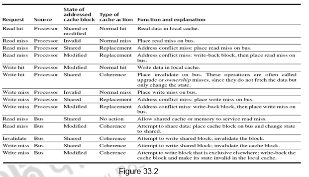
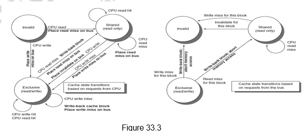
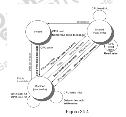
Figure 33.3 shows a finite-state transition diagram for a single cache block using a write invalidation protocol and a write-back cache. For simplicity, the three states of the protocol are duplicated to represent transitions based on processor requests (on the left, which corresponds to the top half of the table in Figure 33.2), as opposed to transitions based on bus requests (on the right, which corresponds to the bottom half of the table in Figure 33.2). The state in each node represents the state of the selected cache block specified by the processor or bus request. Figure 33.3 provides a combined view.
Implementation Complications: Though the protocol discussion seems to be simple, there are a number of complications in the implementatio n. The foremost problem is that the protocol assumes that operations are atomic—that is, an operation can be done in such a way that no intervening operation can occur. For example, the protocol described assumes that write misses can be detected, acquire the bus, and receive a response as a single atomic action. In reality this is not true. Similarly, if we used a switch, as all recent multiprocessors do, then even read misses would also not be atomic. Nonatomic actions introduce the possibility that the protocol can deadlock, meaning that it reaches a state where it cannot continue.
Limitations in Symmetric Shared-Memory Multiprocessors and Snooping Protocols: As the number of processors in a multiprocessor grows, or as the memory demands of each processor grow, any centralized resource in the system can become a bottleneck. In the simple case of a bus -based multiprocessor, the bus and the memory become a bottleneck. So, scalability becomes an issue. In order to increase the communication bandwidth between processors and memory, designers have used multiple buses as well as interconnection networks, such as crossbars or small point-to-point networks. In such designs, the memory system can be configured into multiple physical banks, so as to boost the effective memory bandwidth while retaining uniform access time to memory.
Extensions to the MSI Protocol: The basic MSI protocol is extended by adding other states in order to provide optimizations.
1. The first extension is adding an exclusive state, the MESI (Modified, Exclusive, Shared and Invalid) protocol. The exclusive state is added to indicate a clean block in only one cache. This prevents the need to sending write invalidates on a write, since the block is available only in one cache. The processor merely changes the state to modified. However, when a read miss to the block in the E state occurs, the status has to changed from exclusive to shared, in order to maintain coherence.
2.The other extension that Intel i7 uses is adding an additional state to the MESI protocol, called the Forwarding state, leading to the MESIF protocol. This identifies a sharing cache that will forward the data block, when there is a request. When a cache block is shared by multiple caches, and there is a yet another read miss, the memory can provide the block or one of the caches can provide the data. The cache block, which is designated as the forwarding block, is responsible for forwarding the data. This avoids contention among the various caches in providing data. Also, to make sure the forwarding cache does not replace this block, the forwarding status is granted to the cache that has most recently acquired this block.
3. Yet another extension is the addition of an Owned state indicating that the cache is the owner of the block and is not up to date in memory. This is the MOESI protocol. Normally, when a block in the modified state is shared, the status of both the blocks will be made shared and the block will be written back to memory. But, in the MOESI protocol, the status of the original cache is changed from modified to owned, indicating that the memory does not have a copy and only this cache has the updated copy. It is also the responsibility of this cache to supply the data on a miss. It will write it back to memory when the block is replaced. The AMD Opteron uses the MOESI protocol.
To summarize, we have defined the cache coherence problem in multiprocessors. We have defined the two types of cache coherence protocols. The snoop based cache coherence protocol has been discussed in detail. The implementation issues, the limitations and the extensions to the basic protocol have been discussed.
Web Links / Supporting Materials
- Computer Architecture – A Quantitative Approach , John L. Hennessy and David A.Patterson, 5th Edition, Morgan Kaufmann, Elsevier, 2011.
Cache Coherence II
The objectives of this module are to discuss about the performance of symmetric shared memory multiprocessors in terms of true sharing and false sharing misses and elaborate on the Directory based cache coherency protocol.
In the previous module, we discussed the cache coherence problem and pointed out that there are basically two types of cache coherence protocols. As a recap, the two types are given below:
1. Directory based: The sharing status of a block of physical memory is kept in just one location, called the directory. The directory can also be distributed to improve scalability. Communication is established using point-to-point requests through the interconnection network.
2. Snoop based: Every cache that has a copy of the data from a block of physical memory also has a copy of the sharing status of the block, but no centralized state is kept. The caches are all accessible via some broadcast medium (a bus or switch), and all cache controllers monitor or snoop on the medium to determine whether or not they have a copy of a block that is requested on a bus or switch access. Requires broadcast, since caching information is at processors Useful for small scale machines (most of the market)
The previous module discussed in detail about the snoop based protocol. We will focus on the performance of symmetric shared memory multiprocessors and then elaborate on the directory based approach in this module.
Performance of symmetric shared memory multiprocessors: In a multiprocessor system, several factors affect the performance. We have already looked at the three Cs that contribute to the misses in a uni-processor system – capacity, conflict and compulsory. In addition to these, in a multiprocessor system, we have a fourth miss called the coherence misses. These are the misses that are caused due to inter-processor communication, in order to maintain coherence. We will elaborate on them now.
The coherence misses can be broken into two separate sources. The first source is true sharing misses that arise from the communication of data through the cache coherence mechanism. In an invalidation based protocol, the first write by a processor to a shared cache block causes an invalidation to establish ownership of that block. Additionally, when another processor attempts to read a modified word in that cache block, a miss occurs and the resultant block is transferred. Both these misses are classified as true sharing misses since they directly arise from the sharing of data among processors. The second effect, called false sharing, arises from the use of an invalidation based coherence algorithm with a single valid bit per cache block. False sharing occurs when a block is invalidated (and a subsequent reference causes a miss) because some word in the block, other than the one being read, is written into. If the word written into is actually used by the processor that received the invalidate, then the reference was a true sharing reference and would have caused a miss independent of the block size. If, however, the word being written and the word read are different and the invalidation does not cause a new value to be communicated, but only causes an extra cache miss, then it is a false sharing miss. In a false sharing miss, the block is shared, but no word in the cache is actually shared, and the miss would not occur if the block size were a single word. The following example in Figure 34.1 makes the sharing patterns clear. Let us assume that both X1 and X2 are in the same cache block and processors P1 and P2 have read X1 and X2 before. We shall see what happens for the sequence of operations shown below and classify them each of them as a true sharing miss or a false sharing miss.
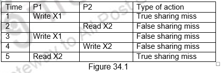
In the first instance, Processor P1 modifies X1. This event is a true sharing miss, since X1 was read by P2 and needs to be invalidated from P2. In the second instance, P2 reads X2, which was earlier invalidated by P1. This event is a false sharing miss, since X2 was invalidated by the write of X1 in P1, but that value of X1 is not used in P2. In the third instance, this event is again a false sharing miss, since the block containing X1 is marked shared due to the read in P2, but P2 did not read X1. The cache block containing X1 will be in the shared state after the read by P2 and a write miss is required to obtain exclusive access to the block. In some protocols this will be handled as an upgrade request, which generates a bus invalidate, but does not transfer the cache block. The fourth event is a false sharing miss for the same reason as step 3. The last event is a true sharing miss, since the value being read was written by P2.
Thus we see that coherence misses have a significant role to play in multiprocessor systems and the effect is more pronounced in the case of tightly coupled systems where a lot of data has be communicated between the processors.
Distributed Shared Memory and the Directory Based Coherence Protocol: We have already discussed the drawbacks of the snoopy protocol. As the number of processors increases, the memory and the communication bandwidths become too demanding and the system is not scalable beyond a certain point. This problem can be overcome by distributing the memory to the various processors. This separates the local memory traffic and the remote memory traffic and the memory demands are greatly reduced. However, in such a case, we also have to eliminate the need for the coherence protocol to broadcast on the bus for every cache miss.
As a result, we have an alternative to the snoopy protocol in the directory based protocol. As the name directory suggests, it is a directory which keeps information about the status of all the blocks in all the caches. Unlike a snoopy protocol where the information was distributed, here the information is available only in the directory and everybody accesses it to obtain details of any block.
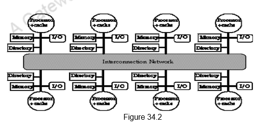
To prevent the directory from becoming the bottleneck, the directory is distributed along with the memory, so that different directory accesses can go to different directories, just as different memory requests go to different memories. A distributed directory retains the characteristic that the sharing status of a block is always in a single known location. This property is what allows the coherence protocol to avoid broadcast. Figure 34.2 shows how a distributed-memory multiprocessor looks with the directories added to each node.
The directory has an entry for each memory block. The amount of information is proportional to the product of the number of memory blocks and the number of processors. We need to track which processors have copies of the block and the status of those blocks in every processor. This is needed for invalidation during a write. The simplest way to do this is to keep a bit vector for each memory block. When the block is shared, each bit of the vector indicates whether the corresponding processor has a copy of that block. We can also use the bit vector to keep track of the owner of the block when the block is in the exclusive state. For efficiency reasons, we also track the state of each cache block at the individual caches.
This overhead is not a problem for multiprocessors with less than about 200 processors because the directory overhead with a reasonable block size will be tolerable. For larger multiprocessors, we need methods to allow the directory structure to be efficiently scaled. The methods that have been used either try to keep information for fewer blocks (e.g., only those in caches rather than all memory blocks) or try to keep fewer bits per entry by using individual bits to stand for a small collection of processors.
Directory Based Cache Coherence Protocol: Just as with a snooping protocol, there are two primary operations that a directory protocol must implement: handling a read miss and handling a write to a shared, clean cache block. (Handling a write miss to a block that is currently shared is a simple combination of these two.) To implement these operations, a directory must track the state of each cache block. In a simple protocol, these states could be the following:
1. Shared – One or more processors have the block cached, and the value in memory is up to date (as well as in all the caches).
2. Uncached – No processor has a copy of the cache block.
3. Modified – Exactly one processor has a copy of the cache block, and it has written the block, so the memory copy is out of date. The processor is called the owner of the block.
Though the states and transitions are the same as that of the snoopy protocol, the actions taken for a transaction are different. Unlike a broadcast that was done in the snoopy protocol, here communication has to be sent from the requesting node to the directory or from the directory to the other nodes. We, therefore, define different types of nodes, depending on their role. They are:
- The local node is the node where a request originates
- The home node is the node where the memory location and the directory entry of an address reside. The physical address space is statically distributed, so the node that contains the memory and directory for a given physical address is known. For example, the high-order bits may provide the node number, while the low-order bits provide the offset within the memory on that node. The local node may also be the home node. The directory must be accessed when the home node is the local node, since copies may exist in yet a third node, called a remote node.
- A remote node is the node that has a copy of a cache block, whether exclusive (in which case it is the only copy) or shared. A remote node may be the same as either the local node or the home node. In such cases, the basic protocol does not change, but inter-processor messages may be replaced with intra-processor messages.
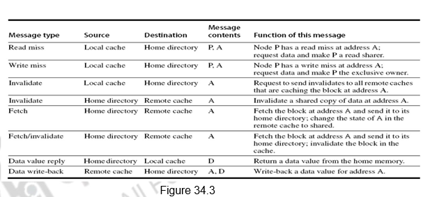
Figure 34.3 shows the messages sent between the processors and the directories for handling misses and also maintaining coherence. The basic operations are the same as that of the snoopy protocol. The interpretation of the messages is given below.
1. The first one is a read miss which is sent from the local cache to the home directory. The format of the message is the processor name P, and the address A. The directory gets the read miss, requests data and includes the processor P in the list of shared nodes.
2. For a write miss, the request goes from the local cache to the home directory. The data is again sent and the processor is made the exclusive owner of the block.
3. The invalidate message is sent from the local cache to the home directory, when the local cache wants to do a write operation.
4. The home directory, in turn, sends invalidates to all remote caches that have cached this address.
5. When a request for a data comes from the local node, the home directory fetches the data from the remote cache and sends it to the local cache. It also includes the local cache in the list of sharers.
6. This happens in response to a write request. The data is fetched by the home directory from the remote cache and the remote cache’s copy is also invalidated.
7. Data value reply is the sending of the data from the home directory to the local cache requesting it.
8. Data write back is the remote cache writing back the data to the home directory. Data value write backs occur for two reasons: when a block is replaced in a cache and must be written back to its home memory, and also in reply to fetch or fetch/invalidate messages from the home. Writing back the data value whenever the block becomes shared simplifies the number of states in the protocol, since any dirty block must be exclusive and any shared block is always available in the home memory.
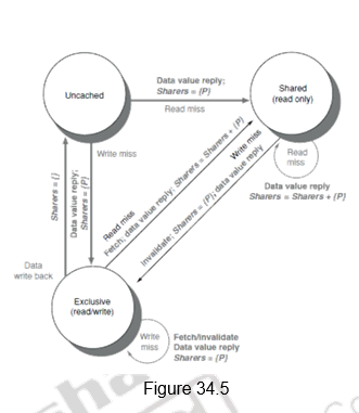
Example Directory Protocol: The operations to be done are the same and the sequence of actions is also the same. The only difference is that, instead of broadcasting the requests on the bus, the requests go to the home directory, which then takes appropriate action. The memory block can be available in an uncached state, i.e., not cached in any cache, shared state, where it is read in one or more caches, or an exclusive state, where it is modified and available in only one block. The details are provided below.
• For uncached block:
– Read miss
• Requesting node puts in a request to the home directory, the directory sends the requested data and is made the only sharing node, and the block is now shared.
– Write miss
• Requesting node puts in a request to the home directory, the requesting node is sent the requested data and becomes the sharing node, block is now exclusive.
• For shared block:
– Read miss
• Requesting node puts in a request to the home directory, the requesting node is sent the requested data from memory, and the node is added to the sharing set.
– Write miss
• Requesting node puts in a request to the home directory, the requesting node is sent the value, all nodes in the sharing set are sent invalidate messages, sharing set only contains requesting node, block is now exclusive.
• For exclusive block:
– Read miss
• Requesting node sends a request to the home directory, the owner is sent a data fetch message, block becomes shared, owner sends data to the directory, data written back to memory, sharers set contains old owner and also the requestor.
– Data write back
• Block becomes uncached, sharer set is empty.
– Write miss
• Message is sent to old owner to invalidate and send the value to the directory, requestor becomes new owner, block remains exclusive.
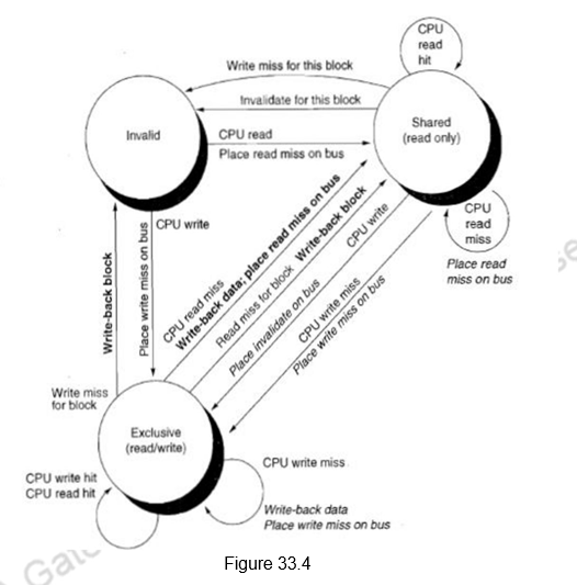
Figure 34.4 shows the state transition diagram for the individual cache blocks in a directory based protocol. Figure 34.5 shows the state transition diagram for the directory. The states and the transitions are the same as discussed earlier.
Just as in the case of snoopy protocols, here also we need to deal with non-atomic memory transactions. The finite buffer sizes will also lead to problems and will have to be handled. The directory protocols used in real multiprocessors contain additional optimizations. In particular, in this protocol when a read or write miss occurs for a block that is exclusive, the block is first sent to the directory at the home node. From there it is stored into the home memory and also sent to the original requesting node. Many of the protocols in use in commercial multiprocessors forward the data from the owner node to the requesting node directly (as well as performing the write back to the home). Such optimizations often add complexity by increasing the possibility of deadlock and by increasing the types of messages that must be handled.
To summarize, we have looked at the performance of symmetric shared memory processors. The true and false sharing misses have been identified. We have looked at the directory based cache coherence protocol that is used in distributed shared memory architectures in detail.
Web Links / Supporting Materials
- Computer Architecture – A Quantitative Approach , John L. Hennessy and David A.Patterson, 5th Edition, Morgan Kaufmann, Elsevier, 2011.
Other Issues with Parallel Processors
The objectives of this module are to discuss about the synchronization issues present in multi-processors and also give an introduction to the various memory consistency models.
We have so far discussed about the various cache coherency protocols that are used to maintain cache coherency in multi-processor systems. But, apart from the cache coherency problem, there are other issues to be handled in a multi-processor system. We shall discuss about them in this module.
In a multi-processor system, where data is being shared by multiple processors, we need to provide synchronization to know when it is safe for different processes to use shared data. In the case of communication through message passing, there is explicit coordination with transmission or arrival of data . However, when communication is through shared address space, additional operations to explicitly coordinate the sharing of data between the various processors are required. For example, enabling a flag, awakening a thread, interrupting a processor, etc. may be required.
Normally, the hardware provides some synchronization primitives and we have software synchronization routines/libraries built based on them. In small scale systems, the most primitive support provided by the hardware is an uninterruptible instruction or an instruction sequence that can atomically retrieve the contents of a memory location and also change it. Software synchronization mechanisms are then constructed using this capability. In larger-scale multiprocessors or high-contention situations, synchronization can become a performance bottleneck because contention introduces additional delays and because latency is potentially greater in such a multiprocessor.
Basic Hardware Primitives: The primary hardware support is the ability to retrieve and change the contents of a memory location. This can be achieved with an atomic exchange, which interchanges a value in a register for a value in memory. Let us assume that we want to build a simple lock, where the value 0 is used to indicate that the lock is free and 1 is used to indicate that the lock is unavailable. A processor tries to set the lock by doing an exchange of 1, which is in a register, with the memory address, which is corresponding to the lock. The value returned from the exchange instruction is 1 if some other processor had already claimed access, and 0 otherwise. In the latter case, the value is also changed to 1, preventing any competing exchange from also retrieving a 0.
For example, consider two processors that each try to do the exchange simultaneously. This race is broken since exactly one of the processors will perform the exchange first, returning 0, and the second processor will return 1 when it does the exchange. The key to using the exchange (or swap) primitive to implement synchronization is that the operation is atomic. The exchange is indivisible, and two simultaneous exchanges will be ordered by the write serialization mechanisms. It is impossible for two processors trying to set the synchronization variable in this manner to assume that have simultaneously set the variable.
Yet another operation, present in many older multiprocessors, is test-and-set, which tests a value and sets it if the value passes the test. For example, an operation that tests for 0 and sets the value to 1 can be used. This is similar to the atomic exchange discussed earlier. Another atomic synchronization primitive is fetch-and-increment. It returns the value of a memory location and atomically increments it. By using the value 0 to indicate that the synchronization variable is unclaimed, we can use fetch-and-increment, just as we used exchange.
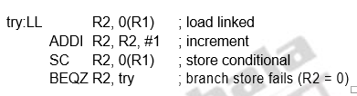
However, implementing a single atomic memory operation introduces some challenges, since it requires both a memory read and a write in a single, uninterruptible instruction. This requirement complicates the implementation of coherence, since the hardware cannot allow any other operations between the read and the write, and yet must not deadlock. An alternative is to have a pair of instructions where the second instruction returns a value from which it can be deduced whether the pair of instructions was executed as if the instructions were atomic. The pair of instructions is said to be atomic if it appears as if all other operations executed by any processor occurred before or after the pair. The pair of instructions includes a special load called a load linked or load locked and a special store called a store conditional. These instructions are used in sequence. If the contents of the memory location specified by the load linked are changed before the store conditional to the same address occurs, then the store conditional fails. If the processor does a context switch between the two instructions, then also the store conditional fails. The store conditional is defined to return 1 if it was successful and a 0 otherwise. Since the load linked returns the initial value and the store conditional returns 1 only if it succeeds, the following sequence implements an atomic exchange on the memory location specified by the contents of R1:
try: MOV R3,R4 ;mov exchange value
LL R2,0(R1) ;load linked
SC R3,0(R1) ;store conditional
BEQZ R3,try ;branch store fails
MOV R4,R2 ;put load value in R4
At the end of this sequence the contents of R4 and the memory location specified by R1 have been atomically exchanged. Any time a processor intervenes and modifies the value in memory between the LL and SC instructions, the SC returns 0 in R3, causing the code sequence to try again.
Similarly, the following example shows how we can implement a fetch &
These instructions are typically implemented by keeping track of the address specified in the LL instruction in a register, called the link register. If an interrupt occurs, or if the cache block matching the address in the link register is invalidated, for example, by another SC, the link register is cleared. The SC instruction simply checks that its address matches that in the link register. If so, the SC succeeds; otherwise, it fails. Since the store conditional will fail after either another attempted store to the load linked address or any exception, we must be careful in choosing what instructions are inserted between the two instructions. In particular, only register-register instructions can safely be permitted. Otherwise, it is possible to create deadlock situations where the processor can never complete the SC. In addition, the number of instructions between the load linked and the store conditional should be small to minimize the probability that either an unrelated event or a competing processor causes the store conditional to fail frequently.
Implementing Spin Locks: Once the atomic exchange primitive is available, we can implement a spin lock using this. A spin lock is one, wherein the processor keeps spinning for a lock, until it becomes available. This is normally used when we expect the lock to be held only for a short duration and the process of acquiring the lock itself does not consume too much time. Otherwise, the processor keeps waiting for a long time. Consider the following code sequence, assuming the lock variables are available in memory:
DADDUI R2, R0, #1
lockit: EXCH R2, 0(R1) ;atomic exchange
BNEZ R2, lockit ;already locked?
Here, we use the atomic exchange instruction. If the exchange happens successfully, R2 will have a value of 0. If R2 has a value of 1, the processor knows that the lock was not acquired, and starts spinning again.
If the multiprocessor system supports cache coherence, we can cache the locks using the coherence mechanism to maintain the lock value coherently. Caching locks has two advantages. First, the process of spinning could be done on a local cached copy rather than requiring a global memory access on each attempt to acquire the lock. The second advantage is because of the fact that there is often locality in lock accesses. That is, the processor that used the lock last will use it again in the near future. In such cases, the lock value may reside in the cache of that processor, greatly reducing the time to acquire the lock. We, accordingly, modify our spin lock procedure. The reads are done on the local copy, and only if the processor knows that the lock is available, it attempts to acquire the lock using a swap. This avoids the number of writes on the shared data. The winning processor executes the code after the lock and, when finished, stores a 0 into the lock variable to release the lock, which starts the race all over again. The following code illustrates the idea:
lockit: LD R2, 0(R1) ; load of lock
BNEZ R2, lockit ; not available-spin
DADDUI R2, R0, #1; load locked value
EXCH R2, 0(R1) ; swap
BNEZ R2, lockit ; branch if lock was not 0
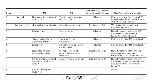
The spin lock mechanism using cache coherence is illustrated in Figure 35.1. Processor P0 has the lock and P1 and P2 are reading the lock status. So, the lock status becomes shared. One of them will be serviced first. When processor P0 releases the lock, it invalidates all other caches. They must fetch the new value to update their copy of the lock. One such cache gets the copy of the unlocked value (0) first and performs the swap. When the cache miss of other processors is satisfied, they find that the variable is already locked, so they must return to testing and spinning.
Barrier Sychronization: Next we shall look at how barrier synchronization is implemented. Barriers are synchronization primitives that ensure that some processes do not outrun others – if a process reaches a barrier, it has to wait until every process reaches the barrier. When a process reaches a barrier, it acquires a lock and increments a counter that tracks the number of processes that have reached the barrier. It then spins on a value that gets set by the last arriving process. This ensures that the processes are allowed to exit the barrier only when all the processes have reached t he barrier.
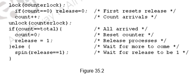
Figure 35.2 shows how barrier synchronization can be implemented. The first processor entering the barrier resets the release and increments the count. As each processor enters the barrier it acquires the lock for count and increments the count value. Once count becomes equal to total, indicating that all the processes have reached the barrier, the barrier is released. Till the count is satisfied, all the processes keep spinning.
But, we have a problem here. If we have two processes, one fast and the other slow. The slow process arrives first, reads release, sees 0 and waits. The fast process arrives, sets release to 1, goes on to execute other code, comes to barrier again, resets release, and starts spinning. The slow now reads release again, sees 0 again and gets stuck. Now, both the processes are stuck and will never leave.
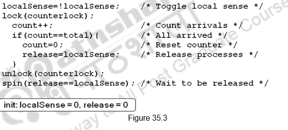
This can be overcome by either counting on the number of processes leaving also, or using a sense-reversing barrier as shown in Figure 35.3. The release in the first barrier acts as the reset for the second. When the fast process comes back, it does not change release, it just waits for it to become 0. The slow eventually sees release is 1, stops spinning, does work, comes back, sets release to 0, and both go forward.
There are many more synchronizations possible. We have discussed only the most primitive ones.
An Introduction to Memory Consistency Models: Another important issue to be handled with multi-processors is memory consistency. We had already outlined the problem in an earlier module. Cache coherence ensures that multiple processors see a consistent view of memory. But, when must a processor see a value that has been updated by another processor, is a question. Since processors communicate through shared variables, the order in which a processor observes the data writes of another processor is important. Since the writes of another processor can only be observed through reads, we will have to decide on the properties that must be enforced among reads and writes to different locations by different processors.
As an example, observe the code sequence below. Here are two code segments from processes P1 and P2:

Assume that the processes are running on different processors, and that locations A and B are originally cached by both processors with the initial value of 0. If writes always take immediate effect and are immediately seen by other processors, it will be impossible for both if statements to evaluate their conditions as true. But suppose the write invalidate is delayed, and the processor is allowed to continue during this delay; then it is possible that both P1 and P2 have not seen the invalidations for B and A before they attempt to read the values. There is an ambiguity about what the programmer had in mind and what is actually happening. Consistency models clarify on these issues. The consistency model defines the ordering of writes and reads to different memory locations. The hardware guarantees a certain consistency model and the programmer attempts to write correct programs with those assumptions.
The most straightforward model for memory consistency is called sequential consistency. Sequential consistency requires that the result of any execution be the same as if the memory accesses executed by each processor were kept in order and the accesses among different processors were arbitrarily interleaved. Sequential consistency eliminates the possibility of some non obvious execution in the previous example because the assignments must be completed before the if statements are initiated.
The simplest way to implement sequential consistency is to require a processor to delay the completion of any memory access until all the invalidations caused by that access are completed. The next memory access has to be delayed until the previous one is completed. Memory consistency involves operations among different variables. The two accesses that must be ordered are actually to different memory locations. We must delay the read of A or B (A = 0 or B = 0) until the previous write has completed (B= 1 or A = 1). Under sequential consistency, we cannot place the write in a write buffer and continue with the read.
Sequential consistency is very easy to understand and presents a very simple programming model. However, it does not allow many of the optimizations and so the performance will get affected. It is the simplest, yet the strictest consistency model. A better implementation would be for the processor to issue accesses as it sees fit, but detect and fix potential violations of sequential consistency.
The challenge lies in developing a programming model that is simple and at the same time gives good performance. For example, we can assume that programs are synchronized, wherein all access to shared data are ordered by synchronization operations that we discussed earlier. A data reference is ordered by a synchronization operation if, in every possible execution, a write of a variable by one processor and an access (either a read or a write) of that variable by another processor are separated by a pair of synchronization operations, one executed after the write by the writing processor and one executed before the access by the second processor. In case of variables being updated without ordering by synchronization, this will lead to data races because the execution outcome depends on the relative speed of the processors and the outcome is unpredictable. So, we need to write synchronized programs that are data-race-free.
Programmers can write their own synchronization mechanisms, but this is not guaranteed to work and can lead to buggy programs. Therefore, typically all programmers will choose to use synchronization libraries that are correct and optimized for the multiprocessor and the type of synchronization. Also, the use of standard synchronization primitives ensures that even if the architecture implements a more relaxed consistency model than sequential consiste ncy, a synchronized program will behave as if the hardware implemented sequential consistency.
Relaxed Consistency Models: The key idea in relaxed consistency models is to allow reads and writes to complete out of order, but to use synchronization operations to enforce ordering, so that a synchronized program behaves as if the processor were sequentially consistent. There are a variety of relaxed models that are classified according to what read and write orderings they relax. Sequential consistency constraints can be relaxed in the following ways (allowing higher performance):
- within a processor, a read can complete before an earlier write to a different memory location completes
- within a processor, a write can complete before an earlier write to a different memory location completes
- within a processor, a read or write can complete before an earlier read to a different memory location completes
- a processor can read the value written by another processor before all processors have seen the invalidate
- a processor can read its own write before the write is visible to other processors
We specify the orderings by a set of rules of the form X→Y, meaning that operation X must complete before operation Y is done. Sequential consistency requires maintaining all four possible orderings: R→W, R→R, W→R, and W→W. The relaxed models are defined by which of these four sets of orderings they relax:
- Relaxing the W→R ordering yields a model known as total store ordering or processor consistency. Because this ordering retains ordering among writes, many programs that operate under sequential consistency operate under this model, without additional synchronization.
- Relaxing the W→W ordering yields a model known as partial store order.
- Relaxing the R→W and R→R orderings yields a variety of models including weak ordering, the PowerPC consistency model, and release consistency, depending on the details of the ordering restrictions and how synchronization operations enforce ordering.
Thus, by relaxing different orderings, the processor can possibly obtain significant performance advantages.
To summarize, we have discussed the synchronization issues associated with multi-processors. We have discussed the primitive atomic exchange instruction supported by the hardware and looked at how this can be used to build various synchronization primitives like simple locks, spin locks and barrier synchronization. We also had an introduction to memory consistency models.
Web Links / Supporting Materials
- Computer Architecture – A Quantitative Approach , John L. Hennessy and David A.Patterson, 5th Edition, Morgan Kaufmann, Elsevier, 2011.
Thread Level Parallelism – SMT and CMP
The objectives of this module are to discuss the drawbacks of ILP and the need for exploring other types of parallelism available in application programs and exploit them. We will discuss what is meant by thread level parallelism and discuss the concepts of Simultaneous Multi Threading and Chip Multi Processors.
So far, we have looked at various hardware and software techniques to exploit ILP. The ideal CPI that we can expect in a pipelined implementation is only 1. We looked at different techniques to avoid or minimize the stalls associated with the various hazards. The performance of a pipelined implementation can be improved by deepening the pipeline or widening the pipeline. Deepening the pipeline increases the number of in-flight instructions and decreases the gap between successive independent instructions. However, it increases the gap between dependent instructions. There is an optimal pipeline depth depending on the ILP in a program and it is a design issue. It may be tough to pipeline some structures and there may be an increase in the cost of bypassing. Increasing the width of the pipeline, as in the case of multiple issue processors also has its own problems and difficulties. It may be difficult to find more than a few, say, four independent instructions to issue and it may be difficult to fetch more than six instructions and there is also an increase in the number of ports per structure.
In order to reduce the stalls associated with fetch, we may have to employ better branch prediction methods with novel ways to index/update and avoid aliasing and also cascade branch predictors. The other option is to use a trace cache. Instead of limiting the instructions in a static cache block to spatial locality, a trace cache finds a dynamic sequence of instructions including taken branches to load into a cache block. The name comes from the cache blocks containing dynamic traces of the executed instructions as determined by the CPU rather than containing static sequences of instructions as determined by memory. Hence, the branch prediction is folded into cache, and must be validated along with the addresses to have a valid fetch. The Intel Netburst microarchitecture, which is the foundation of the Pentium 4 and its successors, uses a trace cache. The trace cache has a lot of shortcomings, but is very useful in handling the limitations of the fetch unit. In Intel processors, the trace cache stores the pre-decoded instructions.
Limitations of ILP: Inspite of all the hardware and software techniques employed to exploit ILP, there is a limit to how much we can exploit ILP. First of all, there is a limitation with the hardware that we use. The number of virtual registers that we actually have is limited, not infinite, to do the renaming process. The branch predictors and jump predictors that we use may not be perfect. Similarly, we may not be able to resolve memory address disambiguities always. In short, we do not have an idealistic processor, limited only by true data dependences and without any control, WAR and WAW hazards.
Doubling issue rates above today’s 3-6 instructions per clock, say to 6 to 12 instructions, probably requires a processor to issue 3 or 4 data memory accesses per cycle, resolve 2 or 3 branches per cycle, rename and access more than 20 registers per cycle, and fetch 12 to 24 instructions per cycle. The complexity of implementing these capabilities is likely to mean sacrifices in the maximum clock rate. For example, one of the widest issue processors is the Itanium 2, but it also has the slowest clock rate, despite the fact that it consumes the most power. Most techniques for increasing performance also increase the power consumption. Multiple issue processors techniques all are energy inefficient. Issuing multiple instructions incurs some overhead in logic that grows faster than the growth in issue rate. There is also a growing gap between the peak issue rates and sustained performance, which leads to increasing energy per unit of performance.
Exploiting other types of parallelism: The above discussion clearly shows that ILP can be quite limited or hard to exploit in some applications. More importantly, it may lead to increase in power consumption. Furthermore, there may be significant parallelism occurring naturally at a higher level in the application that cannot be exploited with the approaches used to exploit ILP. For example, an online transaction processing system has natural parallelism among the multiple queries and updates that are presented by requests. These queries and updates can be processed mostly in parallel, since they are largely independent of one another. This higher level parallelism is called thread level parallelism because it is logically structured as separate threads of execution. A thread is a separate process with its own instructions and data. A thread may represent a process that is part of a parallel program consisting of multiple processes, or it may represent an independent program on its own. Each thread has all the state (instructions, data, PC, register state, and so on) necessary to allow it to execute. Unlike instruction level parallelism, which exploits implicit parallel operations within a loop or straight-line code segment, thread level parallelism is explicitly represented by the use of multiple threads of execution that are inherently parallel.
Thread level parallelism is an important alternative to instruction level parallelism, primarily because it could be more cost-effective to exploit than instruction level parallelism. There are many important applications where thread level parallelism occurs naturally, as it does in many server applications. Similarly, a number of applications naturally exploit data level parallelism, where the same operation can be performed on multiple data. We shall discuss about exploiting data level parallelism in a later module.
Since ILP and TLP exploit two different types of parallel structure in a program, it is a natural option to combine these two types of parallelism. The datapath that has already been designed has a number of functional units remaining idle because of the insufficient ILP caused by stalls and dependences. This can be utilized to exploit TLP and thus make the functional units busy. There are predominantly two strategies for exploiting TLP along with ILP – Multithreading and its variants, viz., Simultaneous Multi Threading (SMT) and Chip Multi Processors (CMP). In the case of SMT, multiple threads share the same large processor which reduces under-utilization and does efficient resource allocation. In the case of CMPs, each thread executes on its own mini processor, which results in a simple design and low interference between threads. We will discuss about both these approaches.
Multithreading: Multithreading allows multiple threads to share the functional units of a single processor in an overlapping fashion. In order to enable this, the processor duplicates the independent state of each thread – a separate copy of the register file, a separate PC, and a separate page table. The memory itself can be shared through the virtual memory mechanisms, which already support multiprogramming. In addition, the hardware must support the ability to change to a different thread relatively quickly; in particular, a thread switch should be much more efficient than a process switch, which typically requires hundreds to thousands of processor cycles.
There are two main approaches to multithreading – Fine grained and Coarse grained. Fine-grained multithreading switches between threads on each instruction, causing the execution of multiple threads to be interleaved. This interleaving is normally done in a round-robin fashion, skipping any threads that are stalled at that time. In order to support this, the CPU must be able to switch threads on every clock cycle. The main advantage of fine-grained multithreading is that it can hide the throughput losses that arise from both short and long stalls, since instructions from other threads can be executed when one thread stalls. But it slows down the execution of the individual threads, since a thread that is ready to execute without stalls will be delayed by instructions from other threads.
Coarse-grained multithreading switches threads only on costly stalls, such as level two cache misses. This allows some time for thread switching and is much less likely to slow the processor down, since instructions from other threads will only be issued, when a thread encounters a costly stall. Coarse-grained multithreading, however, is limited in its ability to overcome throughput losses, especially from shorter stalls. This limitation arises from the pipeline start-up costs of coarse-grain multithreading. Because a CPU with coarse-grained multithreading issues instructions from a single thread, when a stall occurs, the pipeline must be emptied or frozen and then fill in instructions from the new thread. Because of this start-up overhead, coarse-grained multithreading is much more useful for reducing the penalty of high cost stalls, where pipeline refill is negligible compared to the stall time.
Simultaneous Multithreading: This is a variant on multithreading. When we only issue instructions from one thread, there may not be enough parallelism available and all the functional units may not be used. Instead, if we issue instructions from multiple threads in the same clock cycle, we will be able to better utilize the functional units. This is the concept of simultaneous multithreading. We try to use the resources of a multiple issue, dynamically scheduled superscalar to exploit TLP on top of ILP. The dynamically scheduled processor already has many HW mechanisms to support multithreading –
- a large set of virtual registers that can be used to hold the register sets of independent threads
- register renaming to provide unique register identifiers, so that instructions from multiple threads can be mixed in the data-path without confusing sources and destinations across threads and
- out-of-order completion that allows the threads to execute out of order, and get better utilization of the HW.
Thus, with register renaming and dynamic scheduling, multiple instructions from independent threads can be issued without regard to the dependences among them. The resolution of the dependences will be handled by the dynamic scheduling capability. We need to add a renaming table per thread and keep separate PCs. The independent commitment of each thread can be supported by logically keeping a separate reorder buffer for each thread. Figure 24.1 shows the difference between the various techniques.
In the superscalar approach without multithreading support, the number of instructions issued per clock cycle is dependent on the ILP available. Additionally, a major stall, such as an instruction cache miss, can leave the entire processor idle. In the fine-grained case, the interleaving of threads eliminates fully empty slots. Because only one thread issues instructions in a given clock cycle, however, ILP limitations still lead to a significant number of idle slots within individual clock cycles. In the coarse-grained multithreaded superscalar, the long stalls are partially hidden by switching to another thread that uses the resources of the processor. Although this reduces the number of completely idle clock cycles, within each clock cycle, the ILP limitations still lead to idle cycles. Furthermore, in a coarse-grained multithreaded processor, since thread switching only occurs when there is a stall and the new thread has a start-up period, there are likely to be some fully idle cycles. In the SMT case, TLP and ILP are exploited simultaneously, with multiple threads using the issue slots in a single clock cycle. Ideally, the issue slot usage is limited by imbalances in the resource needs and resource availability over multiple threads. In practice, other factors—including how many active threads are considered, finite limitations on buffers, the ability to fetch enough instructions from multiple threads, and practical limitations of what instruction combinations can issue from one thread and from multiple threads—can also restrict how many slots are used.

The other option that we need to discuss to exploit TLP and ILP is Chip Multi Processors (CMPs). Instead of looking at a powerful processor that might be a dynamically scheduled superscalar with support for speculation and also SMT, can we look at a simpler processor, but multiples of them? That is what CMPs stands for – several processors on a single chip. Each processor can individually support a thread of execution. Thus, with multiple processors, we have several threads of execution. These processors can have both shared and distributed memory architectures and they may be made up of both homogenous and heterogeneous processor types. Having several processors on the same chip reduces the wire delays. Since the processors are just replicated in most of the cases (homogenous), the very long design and verification times needed for modern complicated processors is avoided. The difference between an SMT processor and a CMP can be summarized as follows:
SMT:
- Pool of execution units (wide machine)
- Several Logical processors
- – Copy of state for each of these logical processors
- – Multiple threads run concurrently
- – Better utilization and latency tolerance
CMP:
- Simple Cores
- – Moderate amount of parallelism
- – Threads are running concurrently on different cores
- Chip Multiprocessors integrate multiple processor cores on a single chip
- Eases the physical challenges of packing and interconnecting multiple processors
- This kind of tight integration reduces off-chip signaling and results in reduced latencies for processor-to-processor communication and synchronization.
- CMPs use relatively simple single-thread processor cores to exploit thread-level parallelism with one application by executing multiple threads in parallel across multiple processor cores.
- Allows a fairly short cycle time.
- Reduces the hardware overhead.
- Reduces power consumption.
- CMP is an ideal platform to run multiprogrammed workloads or multithreaded applications. However, CMP architecture may lead to resource waste if an application cannot be effectively decomposed into threads or there is not enough TLP.
To summarize, we looked at the limitations of ILP and the need for exploiting other types of parallelism like TLP and data level parallelism. There are basically two ways of exploiting TLP – multithreading and CMPs. We discussed the different types of multithreading – fine-grained multithreading, coarse-grained multithreading and simultaneous multithreading. Instead of using a complicated processor, the other option is to look at simple, multiple processors which execute multiple threads of execution. We also discussed the comparison between these two types of processors.
| Web Links / Supporting Materials |
| Computer Organization and Design – The Hardware / Software Interface, David A. Patterson and John L. Hennessy, 4th Edition, Morgan Kaufmann, Elsevier, 2009. |
| Computer Architecture – A Quantitative Approach , John L. Hennessy and David A. Patterson, 5th Edition, Morgan Kaufmann, Elsevier, 2011. |